EMRI AUTOPILOT – Optimal control for safe and efficient steering
The EMRI Autopilot SEM300 provides excellent quality in steering and control, with optimal routing and low fuel consumption as a result.
- Type approved with Furuno FMD ECDIS, Track control
- Adaptive Autopilot modes
- Course Mode for automatic drift compensation
- NAUT AW compliant with a standby unit
- Curved EBL – shown on ECDIS
- Alarm interface for Bridge Alarm Management
- Intuitive operation
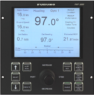
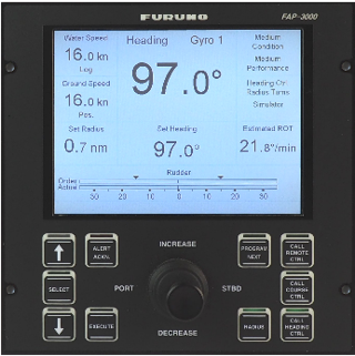
- 6.5 inch TFT display with high luminance
Design
SEM300 is based on many years of experience in cost-efficient and safe Autopilot design. It is designed with a tiller on the control panel, where the navigator can directly change set point, both heading and radius. The panel is designed with push buttons that have an LED backlight and an LED lightbar above each button. The lightbar clearly indicates which mode is in use, so operation can be done safely. The navigator is never in doubt when an order is given due to the required actuation force of both tiller and pushbuttons.
To ensure the best experience and readability on the display at all times, the navigator can choose between day, dusk and night view.
Key information displayed:
- Speed information, water and ground speed
- Rudder order
- Actual rudder (if feedback is provided)
- Clear indication of rudder limits
- Heading, Set Heading
- Actual Gyro in use
- Chosen performance mode
- Course mode (when course mode is used)
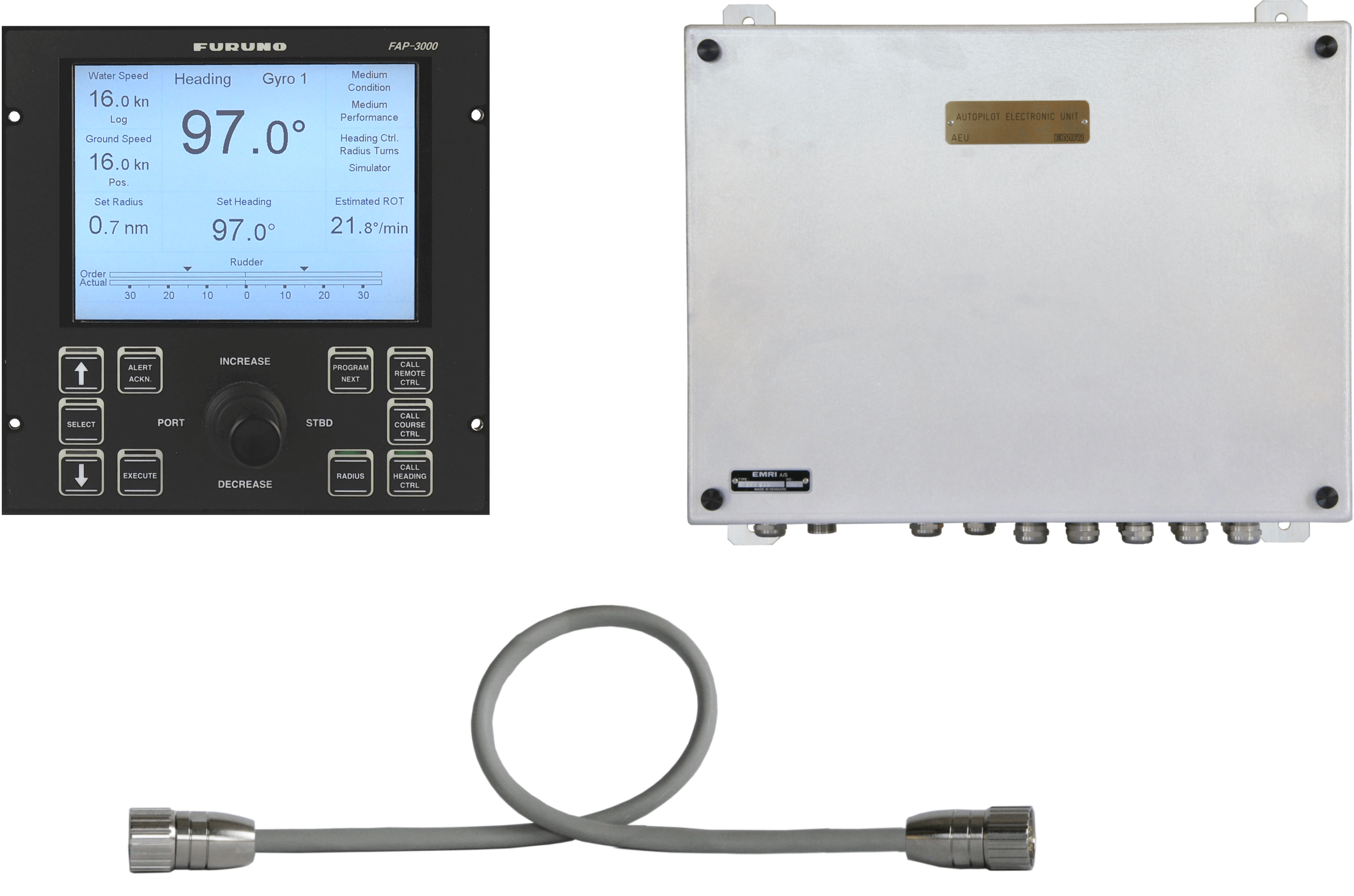
SEM300 consists of:
- Autopilot Control Panel (MIP211)
- Autopilot Cable (CE2MM)
- Autopilot Electronic Unit (AEU611)
Adaptive Autopilot modes
SEM300 has two sets of adaptive modes to help with fuel efficiency and steering optimization. The Autopilot adapts its performance based on the choice made by the navigator.
Precise, Medium and Economy
Three options are available, depending on how tight the vessel needs to follow the set heading. Economy mode provides the most relaxed, fuel-saving heading control by minimizing the use of rudder movements.
Loaded, Medium and Light
Three options are available, depending on the vessel´s loaded condition. The Autopilot will automatically optimize the steering based on the chosen condition.
Flexible design options
The Autopilot can have up to 4 control panels connected to the same AEU (Autopilot Electronic Unit) in case more panels are requested.
In SEM300 new parameter settings can be uploaded directly to the Autopilot via USB key. It makes it quick and easy to make adjustments if needed.
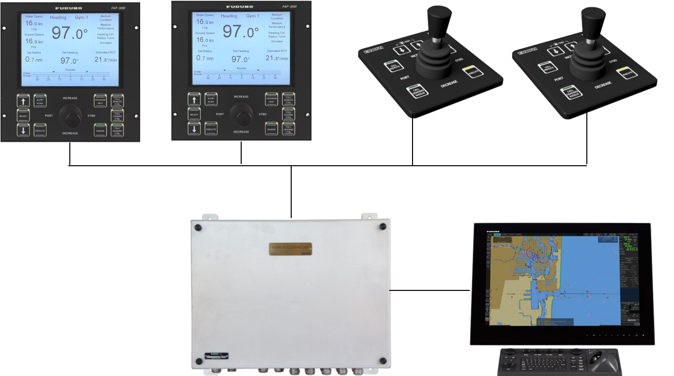
Armrest CONTROL
Steering from the navigator´s chair is possible with an Armrest Panel that is designed for easy control of the essential Autopilot functions while adding better ergonomics for the navigator.
In order to ensure safety and avoid any possible confusion by the navigator, the Armrest Panel has similar layout and functional style as the autopilot control panel. It is operated by the use of pushbuttons with an actuation force of 5.5N and a rocker tiller designed to avoid any unwarranted actions.
The Armrest Panel is installed directly to the Autopilot Electronic Unit via CAN-bus terminals or through a junction box.
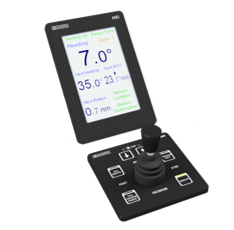
Armrest display (coming soon)
![]()
A 5-inch vertical Armrest display that can be built into the same front plate for a slim line control panel.
Setup
SEM300 is preset from the factory, where parameters are loaded into the Autopilot based on known ship data. This makes setup and sea trial simple. The preset is done with decades of experience in the field and acknowledged steering performance.
If requested, additional finetuning can be performed by a service engineer. Useful setup wizards are available and provide extensive opportunities for adjusting to specific individual preferences and vessel steering capabilities.
Retrofit
SEM300 offers an improved human-machine interface with extensive opportunities in its design and functionality. Retrofitting from SEM200 or Furuno FAP-2000 to SEM300 does not require any console work, as the equipment is designed to fit into the existing cut-outs onboard. We can identify and deliver the correct Autopilot setup based on known ship data, making it as simple as possible for the crew onboard. This makes it cost-efficient, while also minimizing the time needed to perform the retrofit.
Older/other Autopilots can be retrofitted to SEM300 by performing an observation of the existing system.
Standard mounting
The control panel is usually mounted in the bridge console cutout by using the four mounting holes.
Plugged mounting option
The mounting holes are plugged, and the control panel can be mounted in the console from the bottom up in order to create a visually streamlined look in the console.
Advantages of retrofitting
- Improved display
- More relevant information is provided for the navigator
- Course Mode
- Improved Programming Mode
- Rudder Toe angle – better fuel economy for dual rudder vessels
- Product lifetime considerations
- More bridge design options
- Improved service tools
Rudder Toe Angle
For dual rudder vessels, SEM300 can display the Toe angle on the control panel. When using Toe angle control of the rudders, it is possible to optimize the fuel consumption by avoiding loss of propulsion.
Programming Mode
The navigator can plan changes ahead by programming next heading, next course or next radius which is stored in the Autopilot and ready to be executed. It is especially useful when navigating in narrow waters such as the archipelagoes.
When programming the next settings, the navigator can keep the actual settings available in the background and thereby be able to make an easy swap between modification of ongoing maneuvers and programming mode. The Autopilot control panel clearly and logically displays the step-by-step programming using the terminology “next” to avoid any possible confusion.
Course Mode
Besides Heading and Track control, SEM300 can be used in Course Mode which is a drift-compensated heading control. No manual corrections are necessary, as the Autopilot automatically compensates for any drift by using the Gyro as a dynamic reference and GPS signal as a static reference to stay on course.
Heading control
Classic heading control will maintain the set heading making it necessary for the navigator to manually compensate for any drift to stay on course.

Course Mode
When operating in Course Mode the Autopilot will compensate for any drift by automatically adjusting the actual heading to stay on course.

EMRI JS/DP – Automatic position keeping for safe and efficient maneuvering
- Automatic and Manual Control
- Flexible Console Design
- Customizable Panel Options
- Training Mode
- Intuitive Operation
- Limited Time needed for Sea Trial
- Easy to Read High Brightness Display
The Joystick/Dynamic Positioning System from EMRI provides excellent maneuvering capabilities with user-friendly modes of operation.
The Joystick/Dynamic Positioning system is based on many years of experience with the design of intuitive and safe navigation equipment together with an extensive database of ship models. Every system is thoroughly tested at the factory before delivery, to ensure high-standard performance and to save valuable time during the sea trial. This is typically performed and approved with an onboard visit length of one or two days.
The JS/DP panel is designed with a programmable, high-brightness display with day and night view, which gives the navigator relevant information at all times during maneuvering with the easy-to-use automatic and manual control modes.
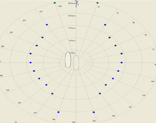
Capability Plots
The EMRI Joystick/Dynamic Positioning System is preceded by a series of Capability Plots. This is a polar diagram of the ship & the system’s ability to resist wind and current.
EMRI’s capability plots are computer simulations, examining the delivered control system’s performance against theoretical vessel specifications.
FLEXIBLE CONSOLE DESIGN
On Cruise Liners and Giga Yachts with plenty of console space, the EMRI JS/DP panels can be directly dropped down in the cut-outs on the consoles for easy “plug’ n play”.
On Mega Yachts with tighter console design, the JS/DP panels can be integrated into the overall foil design, utilizing a common layout of buttons, texts and lamps. The system thereby appears to be a nicely integrated shipyard design.
TRAINING
Whenever the vessel is alongside the crew can perform onboard training with the system, or at sea depending on the number of control panels. Data collected during the sea trial is used in a built-in computer model, providing a realistic setting when using the training mode
DP DISPLAY
The Dynamic Positioning display application can be shown on the navigation system supplier’s computer or a computer-delivered by EMRI.
VDU pictures are designed for each vessel’s maneuver devices.
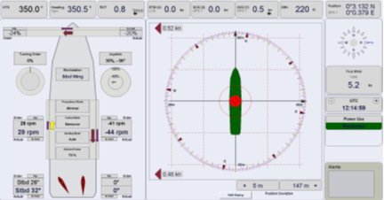
CONTROL MODES
The Joystick/Dynamic Positioning System provides the navigator with a set of control features that are simple and safe to use.
Maneuver Control
Can be used for manual steering using the joystick when performing low-speed maneuvering e.g., in and out of ports. In order to assist the navigator, the system offers an Auto Heading feature and a Wind Correct feature. When activated, the vessel will automatically maintain the set heading and compensate for impacts caused by the wind.
DP Control
By the use of thrusters and rudders, the system ensures that the vessel will maintain a specific position when Dynamic Positioning is activated. In DP Control, the navigator can choose to use the Auto Heading feature, which will automatically keep the vessel at the specified heading or use the Wind Heading feature, to automatically set the vessel up against the wind in order to optimize fuel consumption during position keeping.
When in DP Control the navigator can plan the next maneuver by getting a visualization of the vessel’s movement before the plan is executed. A shadow vessel will be shown on the Dynamic Positioning display application using the actual vessel position as a reference.
RELAXED MODE
In order to achieve better fuel efficiency, the system has a relaxed steering feature, which can be activated when using Maneuver control or DP control. In Maneuver control, it provides the most relaxed fuel-saving heading keeping, by minimizing the use of rudder movements. In DP control it will allow the vessel to drift around in a larger specified radius, thereby minimizing the use of power to keep the vessel at a precise spot.

SERVICE TOOLS
The system performs continuous logging of machine interface and navigation data for remote upgrading and service. All it requires is a laptop, an ethernet cable and a trained ETO.
Panel options
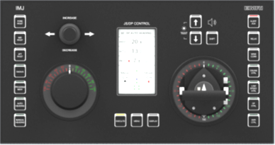
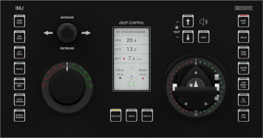
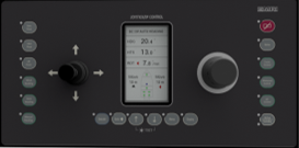
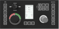
The IMJ series of panels are designed to be customizable by offering different panel layouts for individual users. The simplest panels are operated by a joystick and a tiller while more complex panels can have a mini wheel for turning power or steering control, or an Azimuth lever if that is desired. The panels are designed so they can easily replace old systems for improving the human-machine interface with minimum change to how the system is operated.
Large panel integration
Levers, display and pushbuttons can be delivered as individual modules to be built into the yard- or owner-specific console layouts. The modules can be mounted in the console from the bottom up in order to create a visually streamlined look in the console.
Lever options
Levers from various makers can be used to fulfill special design needs if the electrical interface is approved. Panels can also be designed with el-shaft-controlled levers in the system.
Push button options
A special push button design may be developed to fit a uniform bridge design.
Portable option
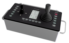
The portable panel is hooked on bulkhead or railing-mounted hooks. The panel can be used on multiple workstations, limiting the needed number of panels for minimizing costs and needed console space. It can be stowed away, when not used.
The portable panel is watertight and delivered with a rugged cable with rugged connectors to make it more robust against wear.
EMRI Steering Control System (SCS)
EMRI has vast experience in ship steering, and we have made many components for a large variety of vessels for the past 50 years. Some may only be suited for retrofits depending on type approval regulations, but do not hesitate to contact us for a free consultancy session on your case.
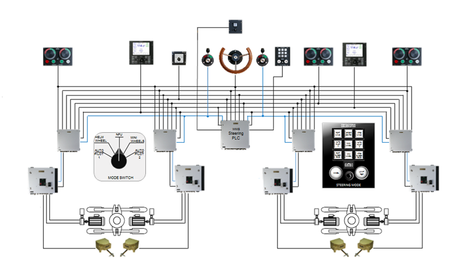
The basic building blocks in an EMRI Steering Control System are:
NAVIGATION ROOM
- WMS (Work Mode Station), the central steering computer (PLC). For larger systems, more WMS units are used as well as separate relay expansion boxes (RSR units)
STEERING GEAR ROOM
- Rudder Control Unit (RCU), the servo units connected to the actual rudder or azimuth steering gear. Several RCU models exist depending on the steering gear brand, such as Mitsubishi and Kawasaki for both proportional or Bang-bang, and ABB and Hatlapa where the RCU is referred to as ACU (Analog Servo Unit)
- Rudder Feedback Units (RFU). These also exist in various types depending on the type of rudder or azimuth system. The original RFU is equipped with a uni-ball link for metal rudder rods, and later versions are adapted for belt drive (RFB) supporting up to 360-degree azimuth operation. The brand new potentiometer kit for RFB360, called RFC360-D, is designed to effectively reduce wear and tear, by using digital angle sensors with no physical contact between moving parts.
BRIDGE
Historically EMRI has produced several operator panels that are used not only for Steering Control but also in conjunction with Autopilots and JS/DP systems.
- Main Steering Wheels
We take pride in having provided steering wheels for 50 years, of which especially our original teak wheels are still fitted in helms ranging from cruise ships to mega-yachts. See details in our Documents section.
- Other Control Units and Indicators
EMRI has a wide range of SCS accessories, such as Mini-wheels, NFU Tillers, Mode switches, Call-up Mode Displays and Rudder Indicators. Check our Resources section for data sheets and other documents.
